Recovering a simple pedagogical tool to determine
the chirality of tetrahedral atoms: The bases and notation of an even number of
exchanges
Aarón
Pérez-Benitez* and Leopoldo Castro-Caballero
Facultad de Ciencias
Quimicas de la Benemérita Universidad Autónoma de Puebla.
14 Sur y avenida San
Claudio. Col. San Manuel. C. P. 72570. Puebla, Pue. México.
E-mail: <aronper@siu.buap.mx>
Keywords: Absolute
configuration, even number exchanges, chiral carbon.
1. Abstract
2. Introduction
3. ENE method: bases and notation
4. Determining the chirality by ENE method
5. Conclusion
6. Bibliography
To determine the chirality sense in tetrahedral atoms is necessary to put the minor priority substituent far from the viewer, but sometimes two-dimensional projections of stereogenic centers do not accomplish this requirement, being necessary to rotate mentally the molecule up to obtain the correct perspective. Instead of that mental procedure (that is quite difficult for many students) an even number of exchanges can be easily done. Bases and notation for this method are provided.
The chirality, from the Greek word chair meaning hand, is the property of an object to be nonsuperimposable with its mirror image. In organic molecules, this property is sometimes due to the presence of a chiral carbon (also named as chiral or stereogenic center), a tetrahedral carbon atom that supports four different substituents (Wade, 2003).
The substituents linked to this atom can only be arranged in the space in two different ways (figure 1). In order to distinguish them, in 1956, Cahn, Ingold and Prelog proposed a system of nomenclature (named “absolute nomenclature"), in which the substituents are classified by priority order: 1>2>3>4 (or a, b, c and d, respectively) (Cahn, 1956), in such way that since a point of view opposed to the substituent of the minor priority (4), the orientation of 1-2-3 occurs in the clockwise or counter-clockwise sense. In the first case the R chiral descriptor is assigned and sigma in the second one (figure 1). These two letters comes from Latin words rectus and sinester, meaning right and left, respectively.
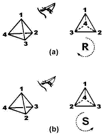
Figure 1. R and sigma chiral descriptors for a stereogenic tetrahedral center depending on the clockwise or counterclockwise rearrangement of 1-2-3 carbon’s substituents (where the priority order is 1>2>3>4 and 4 is located far from the viewer).
However, it is very well known that many students experience difficulties in determining the chirality when the minor priority substituent is not projected far from the viewer. A proof of this fact is the different 2D and 3D attempts aimed to
overcome this difficulty (Aalund, 1986; Ayorinde, 1983; Beauchamp, 1984; Bhushan, 1983; Brun, 1983; Bunting, 1987; Cahn, 1956; Dietzel, 1979; Epling, 1982; Garret, 1978; Idoux, 1982; Mattern, 1985; Reddy, 1989; Siloac, 1999; Thoman, 1976; Wang, 1992; Yongsheng, 1992).
Surprisingly, the same authors (C-I-P) discovered that an Even Number of Exchanges, ENE, between any pair of substituents of a chiral carbon drawn in Fischer’s projection do not alter its absolute configuration and they published this fact in the same article (Cahn, 1956), but they did not give any theoretical nor factual support. That is probably the reason because the ENE method, which is applicable whatever be the chiral carbon’s projection, is not mentioned in the majority of the organic chemistry text books and in consequence many teachers do not know nor use it. So, the bases of the ENE method and three choices to indicate it are presented in this paper.
ENE method: bases and notation
When a chiral center (figure 2a) is reflected on a mirror, sigma1, the arrangement of its substituents is transposed (figure 2b) and it is not superimposable with the original. The initial molecule and the reflected one are named as enantiomers. Note that a new reflection on a sigma2 parallel to sigma1 does the substituents come back to the initial position (figure 2c), meaning that the original enantiomer is obtained.
Figure 2. Reflecting a chiral
tetrahedral center (a): The first reflection, sigma1, inverts its
configuration in (b), while the second one, sigma2, restores it (c
≡ a).
By the
other hand, the original configuration is also obtained if the second
reflection is not applied in the same orientation that the first one, but in
the mirror sigma3 or sigma4
perpendicular to sigma1 (figure 3b-c and
3b-d, respectively).
Figure 3. The application of a second
reflection restores the original configuration of the chiral carbon even if it
is not done on a parallel mirror to the first one. In this case the result of sigma1 followed by sigma4 can be seen directly (d ≡ a), but to check the result of sigma1 followed by sigma3 is necessary to rotate by 180° the molecule c (c = a).
Observe
in figure 4 that the translation and application of sigma1 and sigma3 since the inner
of the molecule give the same result that their application since the outer.
Moreover, the order of the reflections was exchanged to illustrate that the
process is commutative (sigma1 + sigma3 = sigma3
+ sigma1).
At
this point is necessary to introduce a little change in the notation of sigma1, sigma2 and sigma3 because they are
not symmetry but chirality planes. They are labeled in the following as sigman*.
Figure 4. Reflecting a chiral center on the mirrors sigma3* and sigma1* translated
to the inner of the molecule. The labels sigman*
are
used to distinguish these chirality planes from symmetry planes. Contrast with
figure 3a-b-c to check out the commutability of the process.
In
accordance with figures 2-4 is possible to postulate:
“An even number
of reflections carried out onto a chiral molecule does not alter its initial configuration independently of the position and the order of application of the mirrors."
A simple demonstration of this fact can be performed
reflecting a chiral object onto an arrangement of two mirrors having a common
line. At a 0<a<90° angle is possible to appreciate at least one image identical to
the real object (figure 5).
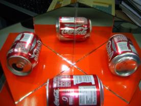
Figure 5. The reflection of a can onto
two mirrors disposed at a 90° angle affords two enantiomorphic images (left and
right) and one image identical (top) to the original object (down).
By the
other hand, the application of sigman* can be seen as a permutation that merely
exchanges ("the place of") two substituents. In the figure
4 for example, the application of sigma3* moves substituent 4 to the position
that substituent 1 was in and vice versa. These permutations (also
called transpositions) are cycles of length two (two-element swaps) and
they are written as a matrix of 2 x n elements, in which 2 is the
number of rows and n is the number of
columns (meaning the number of two-elements swaps). In this manner the
application of sigma3* and sigma1* are equivalent to
the permutation of substituents 4-1 and 2-3 and they are
schematized in figures 6a-b and 6b-c as a 2 x 1 matrices; and sigma3*
+ sigma1* as a 2 x 2 matrix in figure
6a-c. So, there is an analogy between both types of operations: The application
of an even number of them does not alter the initial configuration of a chiral
carbon.
Figure 6. Viewing reflections as permutations whose 2 x 1 and 2 x 2 matrix notation
are equivalent to the application of sigman and sigman
+ sigmam, respectively.
A
second notation to describe a permutation is a two-line representation (figure
7c and 7d), in which the initial position of the substituents is in the first
line (S0) and the final position is in the second line (S1),
in such away that the swaps are symbolized by means of lines or arrows between
them (Tumarello, 2006). Bearing in mind the objective
of the ENE method (to translate the minor priority substituent to the back side),
a little modification was introduced in the initial state with respect to that
normally used in permutation theory: the numbers are written in reverse sense,
it means, in the order 4, 3, 2, 1; in this manner the first swap will always
include the minor priority substituent (e.g. 4 - 1).
With respect to the final state, one of two choices
can be followed:
1). The new position of the substituents is
written just below the old position independently of the order of the numbers
(figure 7c);
2). The order of the numbers is retained (figure
7d).
Although the choice 1 is more direct than 2, probably
this one is more appropriate for our objective because the number of
intersections of the arrows indicates the parity order of the swaps.
Figure 7. Representing the even number
of exchanges as a two-line diagram, in which S0 and S1
are the initial and final positions of the substituents. In choice (c) the new
substituent’s position is just below the old one, while in (d) the order of the
numbers is maintained and the parity order of the swaps is indicated by the
number of intersections of the arrows.
May be the two-line representation is more simple than
the matrix notation when one of the substituents remains unchanged because in
this case is necessary to include a 3-cycle and 1-cycle matrices (figure 8).
For example, if the substituent 2 is not moved in our model
problem, the two notations will be as follows:
Figure 8. The application of an ENE that excludes the
substituent of priority order 2. The whole process of permutations is indicated
at the bottom in the two-line diagram and as a combination of 1-cycle and
3-cycle matrices. 3-cycle matrix means the translation of 4 to 1, 1 to 3 and 3
to 4, and the even parity is got with the swap of 2 with itself.[1]
In a practical sense, a third more pictorial and
simple notation can be introduced: Just indicate the transpositions by means of
curved arrows (figure 9a).
Figure 9. Indicating an even number of transpositions simply
with curved arrows.
Procedure to determine in
2D, the chirality in a given tetrahedral stereogenic center by the ENE method.
Because the ENE method works in
any projection in which the chiral center is given, the procedure is
illustrated this time for an enantiomer of 2-hydroxipropanoic acid drawn in
Fisher’s projection as follows:
1. Interpret the
projection in which the chiral center is given (figure 10a-b).[2]
2. Change chemical
symbols by priority numbers and localize the minor priority substituent (figure
10b-c).[3]
3. Swap the minor priority substituent with
any other localized at the back side (In our example there are two choices: 4-3
and
4-2 transpositions).
4. Swap the other
pair of substituents to restore the initial configuration (In the first choice 2-1 transposition is
done and 3-1 in the second one (figure 10c-d and 10c-e, respectively)).[4]
5. Once the minor
priority is at the back side and an even number of exchange is done, check out
the orientation of 1-2-3 and assign the corresponding chiral descriptor
(figure 10d and 10e).
Figure 10. Illustrating the ENE method to
determine the chirality of an enantiomer of 2-hydroxipropanoic acid, drawn in
Fisher’s projection: In (a-b) the projection is interpreted; in (c) the
substituents are represented by their priority numbers; in (c-d) the ENE is done and in
(d) the chiral descriptor is assigned. Observe that in (c-e) is followed
another possibility to put the minor priority substituent at the back
side.
It is necessary to mention that in a given projection is not always so easy to find and drawn the position of the mirrors that reproduce the exchanges. For example in the last problem the mirror that exchanges 4-3 contains to the substituents labeled 1 and 2 and bisects line 4-3, while the other mirror that exchanges 2-1 contains 3 and 4 and bisects line 1-3. It means that both mirrors are tilted with respect to the plane of the paper and are mutually orthogonal. Fortunately, the same method help us to put the chiral cabon’s substituents in an adequate position to drawn those mirrors in an easily way (figure 11b)
Figure 11. Using the ENE method to find
the positions of the mirrors that exchange the substituents of the chiral
carbon described in figure 10c-d. From this picture (b), the ENE method is applied
to determine the chirality in (c).
Finally, in order to avoid misconceptions it is important to leave in clear that the exchanges between the chiral carbon’s substituents is not a real process as it occurs in other atoms such as in some pentacoordinated phosphorous (Berry, 1960).
The method of Even Number of Exchanges of chiral carbon’s substituents is a very simple way for translating its minor priority substituent to the back side without a lost of its original configuration. It works with any projection in which the tetrahedral stereogenic center was given and the method can be seen as the product of an even number of reflections, independently of the sequence and position of the mirrors.
Finally, the use of any of three notations (two of them coming from permutation theory) for representing the ENE were suggested.
1.
Aalund, M. P.; Pincock, J. A. (1986). “A simple hand method for Cahn-Ingold-Prelog assignment of R and sigma configuration to chiral carbons". J. Chem. Educ. 63, 600.
2.
3.
Beauchamp, P. S. (1984).
““Absolutely" simple stereochemistry". J. Chem. Educ. 61, 666.
4.
5.
6.
7.
Bunting, J. W. (1987).
“Assigning absolute configuration" (L). J. Chem. Educ. 64, 731.
8.
Cahn, R.
S.; Ingold, C. K. y Prelog, V. (1956). Experientia XII [3], 81.
9.
Dietzel, R. A. (1979). “Determination of chiral molecule configuration using
the ±1, 2, 5 Rule". J. Chem. Educ. 56, 451.
10.
Eliel, E. L.; Wilen, S. H.; Mander, L. N. (1994). "Stereochemistry of organic compounds". Wiley. New York.
11.
Epling, G. A. (1982). “Determination of chiral molecule configuration in
Fisher projections". J. Chem. Educ. 59, 650.
12.
Garret, J. M. (1978). “Use of hand models for assigning configurational
nomenclature". J. Chem. Educ. 55, 493.
13.
Idoux, J. P. (1982). “A simple method for specifying the R/S configuration
around a chiral center". J. Chem. Educ. 59, 553.
14.
Mattern, D. L. (1985). “Fingertip assignment of absolute configuration". J.
Chem. Educ. 62, 191.
15.
Reddy, K. R. N. (1989). “Absolutely “Simple" configuration in Fisher projection formula". J. Chem. Educ. 66, 480.
16.
Siloac, E.; Alexander, J. (1999) “Bird-in-the-hand method for determination of
absolute configuration on Fischer projections". J. Chem. Educ. 76, 798.
17.
Thoman, C. J. (1976). “Permanent models for determining absolute configurations".
J. Chem. Educ. 53, 502.
18.
Tumarello, S. (2006). "Andrei Okounkov, des
probabilités a la théorie des cordes". Futura-Sciences. On-line:
http://www.futura-sciences.com/fr/sinformer/actualites/news/t/mathematiques-1/d/mathematiques-andrei-okounkov-des-probabilites-a-la-theorie-des-cordes_9631/. Last visited on: August 24th, 2007.
19.
Wade, L. G. Jr. (2003).
“Organic chemistry". 5ed. Prentice-Hall. New Jersey.
20.
Wang, J-X, Yang, C. (1992). “Determining a chiral molecule’s R/S configuration
using the rule of multiplication". J. Chem. Educ. 69, 373.
21.
Yongsheng, H.; Cailan, W. (1992). “The new method of rapid
determination of chiral molecule configuration: The triangle method". J.
Chem. Educ. 69, 273.
22.
Zassenhaus, H.
(1999). “The Theory of Groups".
Dover. New York.


 Top
Top CEJ Vol. 10, No. 1, Contents